LATEST INFORMATION
PARKING
Due to construction projects located on the east campus (old AMHI property), the parking availability will be temporarily impacted. Effective Tuesday, October 21, 2025, various parking lots on the campus will have different parking designations. Please select the link below for further information. We apologize for any inconvenience to employees and visitors to the campus.
East Campus Parking Plan (PDF 130KB)
Effective Monday, January 6, 2025, the State Parking Garage at the corner of Sewall and Capitol Streets has reopened, excluding the top level. The EV chargers are located on the ground level and are also fully operational. We apologize for any inconvenience this closure has caused.
Additional parking areas are shown on the map (PDF). Please note that Lots A and B and sections of Lot C (per signage in Lot C) are reserved for Legislators.
Available Parking Map (PDF 193KB)
EV Charging Stations in Augusta (PDF 64KB)
Driver ChargePoint Station Map https://driver.chargepoint.com/
EV Charging Guide for State Agencies (PDF 681KB)
STUDIES
MASTER PLANS
- Augusta Area State Facilities Master Plan 2023 (PDF 24,539KB)
- Mackworth Island Conceptual Utilization Master Plan 2023 - Part 1 (PDF 48,141KB), Part 2 (PDF 37,993KB)
Important Links
Leased Space
- Request for Information (RFI)
- Request for Proposal (RFP)
- Request for Proposal (RFP) - Office of State Procurement Services, Business Opportunities
- Request for Qualification (RFQ)
Planning, Design & Construction
Prequalification Lists
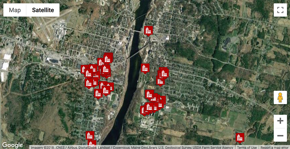
Find our Locations
The online map provides an easy way to locate property under BGS’s portfolio. Click on the icon to view the building’s address and directions.
To view all of the locations in a table format, please click on the link below. You can search all of the locations by name and address.
View locations in table format
Campus Maps
Icons by Maps Icons Collection